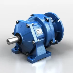
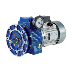
Gearboxes, also known as gear drives, are the arrangement of their shafts or the way that they mount to the driven equipment. However, it is important to realize that shaft arrangement and mounting are two different characteristics of the drive.

Therefore, it is important to know both aspects to successfully determine the best gearbox for your application. The shaft arrangement on a gear drive is the location of the high-speed and low-speed shaft extensions relative to each other.

This is dictated by the position of the motor and driven equipment and is sometimes constrained by the physical space of the application. The orientation of high and low-speed shafts as they relate to the naming of the different types of gear drives may seem very simple, but there are reasons why you would choose one over the others when determining the best gearbox for your application.

The primary determinant for selecting the type of gearbox is space limitations in a system. Because the shafts are oriented differently, your driving equipment, or motor, will be in a different location depending on which type of gear drive is selected.

Benefits & Uses:

IndustriesApplications
AgricultureHeavy duty bulk material handling
AutomotiveHeavy duty process specific
CementWater treatment
EnergyAggregate & construction equipment
ForestGrain handling
Mining
Cement & AggregateLight to medium duty conveying
Sand-GravelBelt conveyors
MiningClassifiers
GrainSeparators
Baggage/Package Handling
Pic-Pac-Retrieval
Energy
Metal Processing
AgricultureConveying
AutomotiveReclaimers/stackers
Cement & AggregateCrushers
EnergyMills
MiningFeeders
Pumps
Dryers
Mixers/blenders
Agitators
Loaders/unloaders
Elevators
AgricultureConveying
Food & BeverageReclaimers/stackers
CementCrushers
ForestMills
MiningFeeders
Pumps
Dryers
Mixers/blenders
Agitators
Loaders/unloaders
Elevators

Technical Specifications

Selection of Heli-Worm Gearbox (Input 1500 RPM)

Model HW-50HW-60HW-70HW-80HW-90HW-110HW-130HW-150
Gear OutputCapacity
RatioI1I2RPM
7532520HP10.701.131.481.902.724.445.948.64
KW10.530.851.111.432.043.334.466.48
T2185299392503720117515732287
DE7474747474747474
M-HP10.330.50.7511.5235
M-KW10.24750.3750.56250.751.1251.52.253.75
M-T2871321992653975297941324
SF2.121212.261.97331.91.813332.221.981.728
9033016.67HP10.590.841.321.662.423.995.358.10
KW10.440.630.991.251.822.994.016.08
T2187267419527769126817002573
DE7474747474747474
M-HP10.330.50.7511.5234
M-KW10.24750.3750.56250.751.1251.52.253
M-T21051592383184776359531271
SF1.787881.681.761.661.613331.9951.7833332.025
12034012.5HP10.430.681.081.311.813.254.106.48
KW10.320.510.810.981.362.443.084.86
T2172272433525725130216432596
DE7070707070707070
M-HP10.250.330.50.7511.51.52
M-KW10.18750.24750.3750.56250.751.1251.1251.5
M-T2100132200301401601601801
SF1.722.06062.161.746671.812.16666672.7333333.24
15035010HP10.340.510.841.131.332.513.505.13
KW10.260.380.630.851.001.882.633.85
T2165248409550647122117032496
DE6868686868686868
M-HP10.250.250.330.50.5122
M-KW10.18750.18750.24750.3750.3750.751.51.5
M-T2122122161243243487973973
SF1.362.042.54552.262.662.511.752.565
1803608.33HP10.270.400.651.001.102.143.134.32
KW10.200.300.490.750.831.612.353.24
T2148220357550604117617202374
DE6464646464646464
M-HP10.250.250.330.50.511.52
M-KW10.18750.18750.24750.3750.3750.751.1251.5
M-T21371371812752755508241099
SF1.081.61.969722.22.142.0866672.16
2103707.14HP10.220.380.590.830.871.852.793.64
KW10.170.290.440.620.651.392.092.73
T2132228355499523111216772188
DE6060606060606060
M-HP10.250.250.330.330.3311.52
M-KW10.18750.18750.24750.24750.24750.751.1251.5
M-T21501501981981986019021202
SF0.881.521.78792.515152.636361.851.861.82
2403806.25HP10.160.260.390.570.741.071.712.45
KW10.120.200.290.430.560.801.281.84
T210417025437248369811161599
DE5757575757575757
M-HP10.250.250.250.250.250.330.50.75
M-KW10.18750.18750.18750.18750.18750.24750.3750.5625
M-T2163163163163163215326489
SF0.641.041.562.282.963.24242423.423.266667

Salient Features

Speed Variations:

By feeding fixed speed to Variator, steeples speed variation can be obtained from

  • Max. Speed = 1.7 x Input speed to
  • Min. Speed = 1/7 x input speed
  • Max.Speed/Min.Speed = 12:1 to 3:1 depending upon selection

_________________________________________________________________

Torque Multiplier:

When speed is reduced, Variators can replace Gear Boxes.

_________________________________________________________________

Speed Multiplier:

Up to 1.7 times input speed without necessity of speed increasing gear.

_________________________________________________________________

High Output Torque – Over Load Capacity:

Up to the standstill of an electric motor of the same power acting as a mechanical clutch.

_________________________________________________________________

High Efficiency:

Overall 85% throughout full speed range ideally used for constant power transmission applications in all types of Industries.

__________________________________________________________________

Speed Holding:

Quite stable with uniform load and within 0.25% with Max. Load.

__________________________________________________________________

Reliability:

Drive is highly reliable with long life as load is equally distributed on number of conical Rollers, which are hardened, and ground to close tolerance.

__________________________________________________________________

Simple Design:
Can be attended by skilled fitter as no electronic/electrical parts/circuits are involved.

__________________________________________________________________
Compactness:
High Power Transmission capacity with small dimensions.

__________________________________________________________________
Speed Control:
Quick and simple. By rotating control knob in running condition only.

__________________________________________________________________
Free From Noise And Vibrations:
No moving parts like Chins, Belts, etc. Drive is through rolling action of PRECISION ROLLERS, which are continuously lubricated. All components are well balanced.

__________________________________________________________________
Bi-directional Rotation Of Output Shaft:
Clockwise/Anti Clockwise depending upon Input shaft rotation, viz. Anti Clockwise/Clockwise respectively.
__________________________________________________________________
Totally Enclosed Unit:
Ideal for hazardous zones.
__________________________________________________________________
Maintenance:
Practically maintenance free. Only ensure proper lubrication.
__________________________________________________________________
Collinear Input & Output Shaft:
In-Line Input and Output Shafts.
__________________________________________________________________
Before Selecting the Variator Consider Following:

Load Factors:

  • Uniform load: 1
  • Medium shock load: 1.5
  • Heavy shock load: 2

Service factors:

  • 8 Hours running – 1
  • 16 Hours running – 1.25
  • 24 Hours running – 1.5

Efficiencies of various driving elements used in drive system.

For frequent start/stop, reversal operation, and high moment of inertia load consult us

____________________________________________________________________

For Further Reduction Use At The Output Shaft Of The Variator:

  • Chain drive (positive)
  • Belt drive (slip occurs) For reduction up to 4:1
  • Suitable reduction gear boxes (worm/helical) by Elmrad

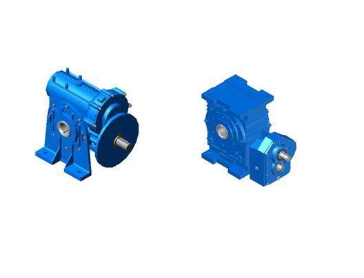
Heli Worm Gear Box Uses and Applications

We shall use fA to designate the application factor (Ca or Ka in AGMA standards and Ka in ISO standards) pr external overload factor deriving from the operating characteristics of the driving and driven engines are defined according to uniform operation. Operation with light shocks and operation with medium shocks: also three classes of driven machine are defined according to uniform loads, medium shock loads, or heavy shock loads. Consult Table 1 for a general explanation.
Table 1 :-
Driven Machine
UMS
Uniform OperationElectric Motors, Turbines, Hydraulic Motors11.251.75
Operation With Light ShocksCombustion engine with 4-6 cylinders1.251.52
Operation With Medium ShocksCombustion engine with 1-6 cylinders1.51.752.25
U = Machine with Uniforms Load
M = Machine with Medium Shock Load
S = Machine with Heavy Shock Load
Application Factors:
Load FactorApplication Sector
U
M
AGITATORS
Uniform Product Density
Variable Product Density
U
M
ALIMENTARY
Mashers, Boilers, Screw feeders,
Blenders, Peelers, Cartoners
(1) U, M
M
S
WINCHES
Lifting
Dragging
Reel Winders
U
M
S
PEPER MILLS
Winders, Dryers, Couch Rolls,
Mixers, Extruders, Thickeners,
Cutters, Glazing Cylinders
M
S
CHEMICAL
Extruders, Printing Presses
Mixers
U
M
M
COMPRESSORS
Centrifugal
Rotating
Axial Piston
M
S
DREDGES
Conveyors
Extractors, Cutter Head Drives
M
M
S
BUILDING
Cement Mixers, Screw Feeders
Crushers, Batchers
Stone Breakers
U
M
M
ELEVATORS
Belt Type, Escalators
Bucket Conveyors, Hoists, Skip Hoists
Public Lifts, Mobile Scaffolding
M
M
(1) U, M
CRANES
Translation
Slew
Lifting
M
M
M
WOOD
Stackers
Transporters
Saws, Thicknessers, Routers
M
M
S
MACHINE TOOLS
Boring Machines, Broaching Machines, Shearing Machines
Bending Machines, Press Forgers
Power Hammers, Rolling Mills
U
M
MIXERS
Uniform Density Product
Variable Density Product
S
M
EARTH MOVING MACHINERY
Rotating Shovel Excavators
Transporters
U
M, S
M, S
PUMPS
Centrifugal
Double Acting Volumetric
Single Acting Volumetric
U
M
CONVEYORS
On rails
Belts
M
M
U
WATER TREATMENT
Screw Feeders, Disintegrators
Mixers, Settlers
Oxygenators
U
M
FAN UNITS
Small
Large

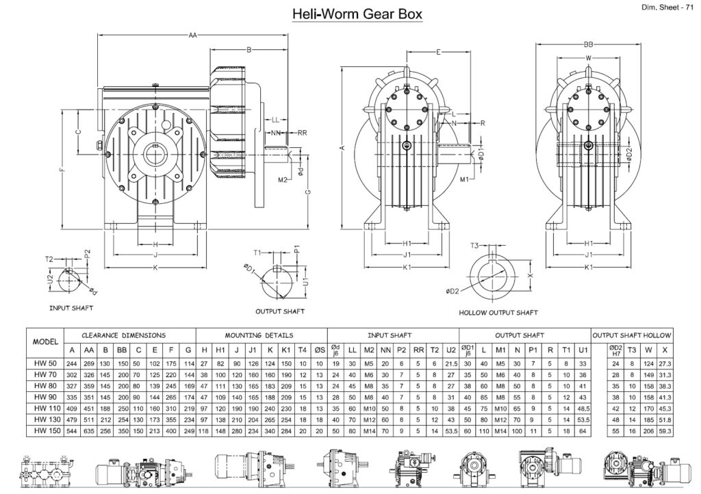
Mounting Dimensions

Share Your Requirements for Customised Solutions! We are Happy to Assist You 🙂

Send message

OUR RANGE OF PRODUCTS

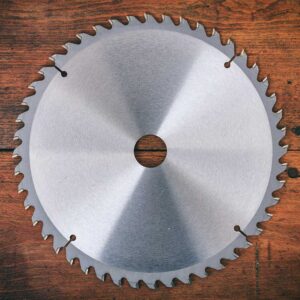
Industrial Blade
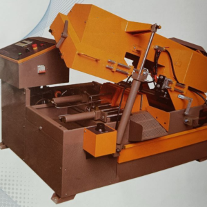
Fully-Automatic